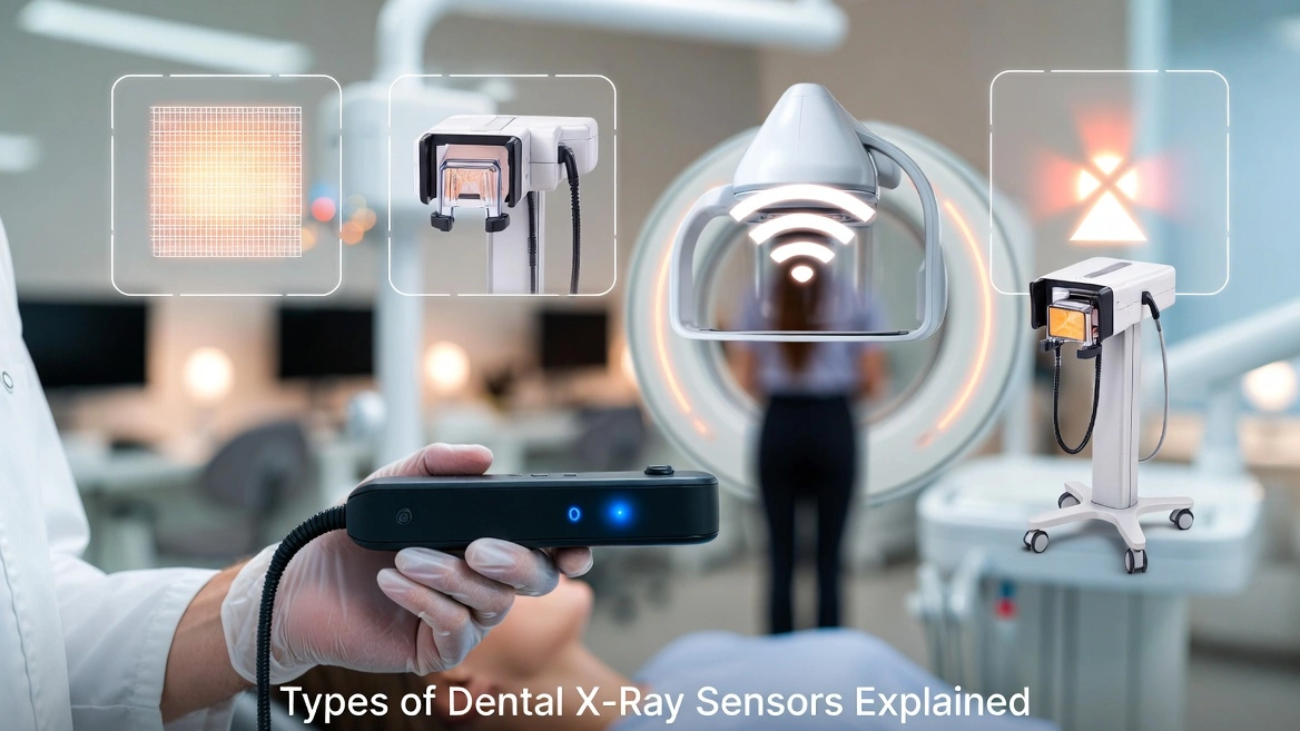
Types of Dental X-Ray Sensors Explained
An exhaustive structural analysis breaking down intraoral receptors, traditional radiation delivery machines, handheld portability variants, and advanced diagnostic 3D imaging infrastructure.
⏱️ 12-15 Min Read
✓ Peer-Reviewed Engineering Data
⚡ Summary of Imaging Modalities
When evaluating the comprehensive landscape of **Types of Dental X-Ray Sensors Explained**, modern diagnostic systems are fundamentally split between **intraoral digital receptors** and **radiation delivery source units**. Intraoral imaging relies on rigid solid-state detectors (**CMOS/CCD**) for instant on-screen rendering or flexible **Phosphor Storage Plates (PSP)** for enhanced structural adaptation. These receptors collect radiation emitted from structural hardware arrays, which range from traditional **wall-mounted units** and **mobile floor-stand systems** to highly responsive **handheld cordless generators** and advanced **3D Extraoral CBCT infrastructure**. Choosing the correct modality directly determines diagnostic resolution, operatory mobility pathways, and overall clinical setup throughput.
1. Digital Intraoral Receptors: CMOS, CCD, and PSP
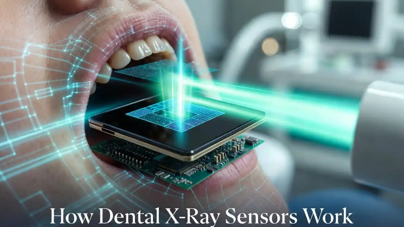
To truly unpack the subject of **Types of Dental X-Ray Sensors Explained**, we must first categorize the digital targets placed directly inside the patient’s oral cavity. These sensors act as the structural receptors that record localized radiation differences as high-energy beams pass through dense bone, enamel, and soft tissue structures.
CMOS (Complementary Metal-Oxide Semiconductor)
The contemporary gold standard for solid-state imaging arrays. **CMOS sensors** integrate active pixel logic, meaning every individual pixel well houses its own micro-transistor configuration to amplify and process incoming data streams on site. This allows for near-instant picture display on operator monitors in under two seconds.
CCD (Charge-Coupled Device)
The foundational heritage platform for early digital radiography systems. **CCD sensors** rely on a sequential transfer mechanism where electrical charges are systematically shifted down rows to a single corner readout node for processing. While delivering excellent uniformity, they are vulnerable to image blooming and higher operational latency.
PSP (Phosphor Storage Plates)
A highly flexible, wireless alternative that mimics traditional film mechanics. **PSP plates** use a photostimulable phosphor coating that records a temporary latent image. The plate is then transferred into an external laser scanner unit that reads and clears the data, trading away instantaneous speed to achieve unmatched patient positioning comfort.
2. Radiation Delivery Structural Mechanics: Wall-Mounted vs. Floor-Stand Mobile Systems
A receptor cannot generate diagnostic value without an optimized source engine. A central theme when examining the diverse **Types of Dental X-Ray Sensors Explained** involves assessing the mechanical delivery systems that support the high-voltage x-ray tubehead inside the operatory.
Traditional Wall-Mounted Tubehead Arrays
The classic structural foundation of modern dental practices. These systems feature an articulating arm anchored securely to wall structural studs. The primary benefit of a **wall-mounted x-ray unit** is its complete lack of a floor footprint, keeping operatory walking lanes clear and providing highly predictable drifting resistance during fine alignment adjustments.
However, these configurations restrict radiation capability to a single chair setup. If a practice layout requires multi-room expansion, significant structural costs are required to mount dedicated units inside every separate operational cove.
Mobile Floor-Stand Systems
Designed specifically for clinics that prioritize multi-chair layout adaptability. A **floor-stand x-ray configuration** features a weighted, heavy-duty wheeled caster base supporting the upright counter-balanced extension arm assembly. This setup allows operatory teams to roll a single high-voltage tubehead engine across different rooms smoothly.
The trade-off involves physical space management. The heavy caster base requires active room storage space and requires clinicians to meticulously handle heavy mechanical paths around baseplates, patient chairs, and floor cords.
3. Handheld Cordless Battery Units
One of the most radical developments within the spectrum of **Types of Dental X-Ray Sensors Explained** is the transition toward absolute cordless portability. Modern **handheld x-ray generators** pack high-capacity lithium-ion battery blocks and dense internal lead shielding directly into a camera-style form factor.
This setup allows the clinician to remain continuously at the patient’s bedside, holding the radiation unit completely free of physical mount bounds. By avoiding the need to step entirely outside the room to fire the exposure switch, patient movement artifacts are significantly reduced—an exceptional benefit when managing pediatric or highly anxious patients.
Radiation Safety Engineering Note: Handheld units protect the operator through a dual-layer strategy: heavy internal insulation to absorb secondary leakage, paired with an external clear lead-filled backscatter shield. This shield generates a precise cone of safety, reflecting deflected photon scatter pathways entirely away from the operator’s hands and torso.
4. Advanced Extraoral 3D Infrastructure: CBCT & Panoramic Systems
As diagnostic requirements grow more complex, intraoral views are combined with extraoral systems that capture comprehensive anatomical structures from outside the patient’s face. These systems represent the absolute peak of modern diagnostic hardware capabilities.
2D Panoramic Tomography Arrays
Provides a continuous, flattened broad view mapping the entire maxillo-mandibular arch, temporomandibular joints (TMJ), and maxillary sinus structures onto a single wide visual field. This is achieved by systematically rotating a linked tubehead and extraoral sensor band around the patient’s head in a synchronized path profile.
3D Cone Beam Computed Tomography (CBCT)
Replaces flat 2D approximations with ultra-precise **3D volumetric datasets**. By casting a cone-shaped radiation beam that acquires hundreds of separate thin-slice profiles in a single sweep, software engines reconstruct complete 3D models. This spatial clarity is mandatory for managing precise implant planning, complex endodontic root configurations, and orthodontic path assessments.
5. Cross-Platform Architectural Matrix
To simplify the procurement and deployment process, this master table synthesizes operational capabilities across all major **Types of Dental X-Ray Sensors Explained**:
| Imaging System Type | Primary Receptor Format | Data Output Velocity | Core Advantage | Primary Operational Limit |
|---|---|---|---|---|
| CMOS Solid-State | Rigid Silicon Active-Pixel Well Matrix | Instantaneous (1.5 to 2 Seconds) | Hyper-fast workflow and excellent theoretical resolution marks | Thick, unyielding casing profile can cause placement discomfort |
| PSP (Phosphor Plate) | Flexible Photostimulable Crystal Sheet | Delayed (Requires external laser scan cycle) | Thin profile matches traditional film shapes and comfort rules | Plates collect physical scratches and require manual handling |
| Wall-Mounted Unit | External Source (Feeds Intraoral Receptors) | Determined by attached sensor format | Zero floor footprint with highly stable drifting resistance | Locked permanently to a single designated operator chair space |
| Mobile Floor-Stand | External Source (Feeds Intraoral Receptors) | Determined by attached sensor format | Enables single tubehead engine sharing across multiple coves | Bulky baseplate footprint requires active room navigation care |
| Handheld Cordless | External Battery Source Array | Determined by attached sensor format | Allows clinician to hold position smoothly at the patient’s side | Requires strict compliance with backscatter shield geometry |
| 3D CBCT Infrastructure | Extraoral Rotating Sensor Panel Base | Processing delay for full 3D rendering | Provides complete 3D volumetric views of anatomical structures | Requires substantial capital layout and specialized facility footprint |
💡 Deepen Your Technical Foundation: Now that you have explored the wide variety of delivery systems and imaging configurations, you can easily examine the deep atomic conversions that convert radiation into clear pixels. Review our companion guide detailing exactly how dental x-ray sensors work to master the underlying physics behind solid-state conversion layers.
6. Frequently Asked Questions
Is a completely wireless intraoral CMOS sensor path options stable?
Yes, modern wireless CMOS systems use secure radio frequency (RF) or direct Wi-Fi local links to move data packets fast. They are completely stable but rely on on-board battery modules, which slightly increases the thickness of the sensor’s perimeter casing.
Why do panoramic and CBCT machines require patients to stand completely still?
Because extraoral systems use an extended data acquisition arc path that takes several seconds to spin around the face, any minor movement can cause ghosting lines or blur artifacts that ruin the entire scan.
Do handheld radiography options pose high health safety risks for operatory teams?
No, as long as the operator holds the device perpendicular to the patient, keeping themselves securely inside the protection path mapped by the external clear lead-filled shield circle.
Optimize Your Practice Radiography Workflow
Whether you need to deploy thin, patient-friendly phosphor plate workflows, robust solid-state CMOS arrays, or nimble handheld emission tech, our specialists can help configure the ideal diagnostic layout.