Understanding Intraoral Sensors
A technical exploration of direct digital radiography, internal scintillator mechanics, chip silicon engineering, and daily calibration protocols.
⏱️ 10-12 Min Read
✓ Verified Engineering Breakdown
⚡ Essential Concept
An **intraoral sensor** is a high-tech electronic receiver placed inside a patient’s mouth to capture digital dental radiographs. Unlike old-fashioned film that requires chemical development, an intraoral sensor converts incoming x-ray energy into light, maps it onto an integrated silicon imaging chip (CMOS or CCD), and transfers high-resolution details directly to your computer screen in under two seconds. Understanding this technology involves knowing how its internal layers manage radiation, why specific chip choices impact detail clarity, and how proper care protects this vital asset.
1. Core Mechanics: How X-Rays Become Images
Modern digital intraoral radiography works through **energy conversion**. The process starts when the dental x-ray tubehead emits targeted photons. These photons pass easily through soft oral tissues but are absorbed by dense enamel, dentin, and bone.
The remaining radiation strikes the intraoral sensor placed inside the mouth. Because silicon imaging chips cannot safely read raw x-rays directly without degrading over time, the sensor uses an internal conversion step. It converts high-energy photons into green or blue visible light, which is then mapped instantly onto a matrix of microscopic pixels.
⚙️ Deep Physics Guide: For an exact, piece-by-piece breakdown of how raw radiation photons interact with electronic plates to form direct digital radiographs, check our companion post explaining how dental x-ray sensors work.
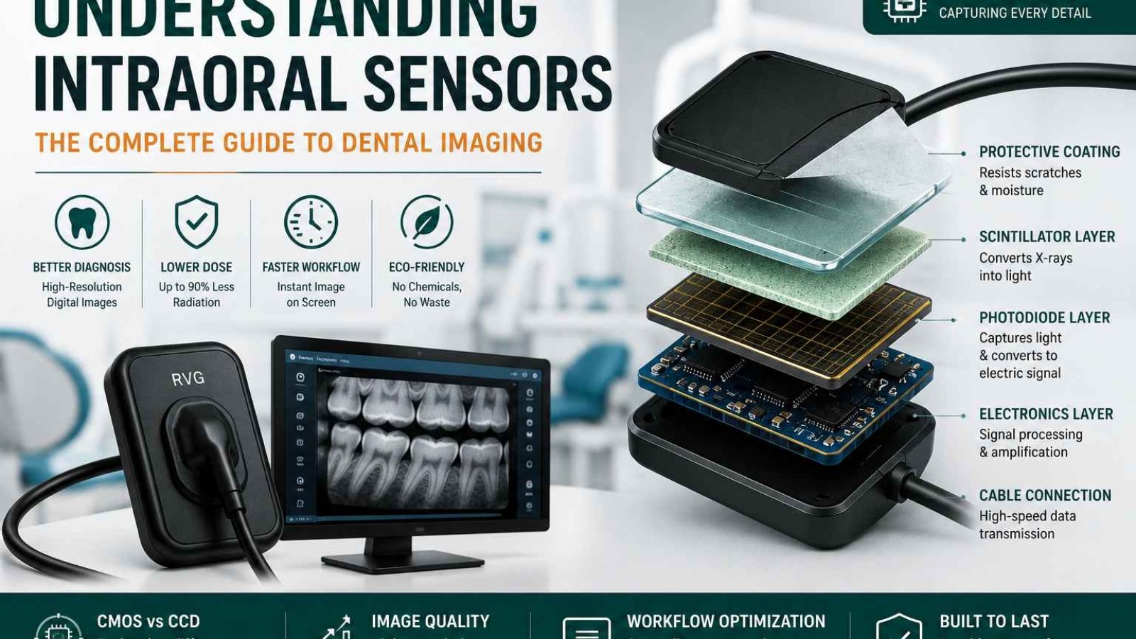
2. Internal Anatomy: Deconstructing Sensor Layers
Though a standard intraoral sensor looks like a single piece of sealed plastic, cutting one open reveals several highly engineered layers stacked closely together:
1. Outer Protective Shell
A rugged, hermetically sealed layer made of high-grade polycarbonate or thermoplastic. This casing shields delicate electronics from saliva, impacts, and chemical disinfectants.
2. Scintillator Screen
Usually made from CsI (Cesium Iodide) or Gd2O2S (Gadolinium Oxysulfide). This crystal matrix catches incoming x-rays and instantly converts them into visible light photons.
3. Fiber Optic Plate (FOP)
An optical guide that channels converted light directly down to the silicon wafer while absorbing stray radiation, protecting the primary imaging chip below.
Beneath these primary layers sits the **silicon imaging chip** itself, resting on a shock-absorbing substrate shield that dampens drop impacts. This entire sandwich of components works in harmony to give you an exceptionally clear diagnostic view.
3. Silicon Engineering: CMOS vs CCD Architectures
When exploring intraoral sensors, you will find two primary chip architectures: **CMOS** and **CCD**. While both convert light photons into electrons, they handle that data differently:
| Architectural Metric | CMOS (Complementary Metal-Oxide) | CCD (Charge-Coupled Device) |
|---|---|---|
| Data Conversion Location | **On-pixel conversion**; processing circuits sit directly on the wafer. | **External conversion**; values shift row-by-row to a corner corner node. |
| Power Consumption Efficiency | Ultra-low power demands; avoids heat generation. | Significantly higher power needs; runs warm during heavy use. |
| Clarity & Spatial Resolution | Exceptional modern resolution (**20 to 25+ lp/mm**). | Solid resolution capabilities (**15 to 18 lp/mm**). |
| Component Integration | High integration; features like USB controllers sit on the same chip. | Requires external support chips, increasing final controller size. |
While older digital sensors relied heavily on CCD configurations, modern setups overwhelmingly use **CMOS technology**. CMOS chips are more power-efficient, cost-effective to manufacture, and offer superior integration, allowing direct-to-USB features inside a smaller housing.
4. Preventing Sensor Failure: Maintenance Protocols
An intraoral sensor is an investment that requires proper care. Because internal connections are fragile, your clinical team should follow these key maintenance habits:
❌ Critical Hazards to Avoid:
- Cable Coiling: Never wrap the connection cable tightly around the sensor body. This twists and breaks internal copper lines.
- Biting Force: Always use proper bite blocks. Never let a patient bite directly on the sensor or its cable.
- Liquid Immersion: Do not submerge sensors in disinfectant baths unless explicitly approved by the manufacturer.
✅ Recommended Care Habits:
- Loose Looping: Hang the cable in loose, wide loops on dedicated wall hooks when not in use.
- Sanitary Sleeves: Always use fresh, customized plastic hygiene sleeves for every exam.
- Gentle Wiping: Disinfect using damp, non-abrasive hospital-grade wipes approved for active electronics.
5. Frequently Asked Questions
What does line pairs per millimeter (lp/mm) mean for image quality?
Line pairs per millimeter (lp/mm) measures a sensor’s spatial resolution. A higher number means the sensor can clearly show lines placed closer together, helping you spot subtle details like hairline tooth fractures or early interproximal decay.
Why do my digital x-ray images look grainy sometimes?
Grainy images usually stem from under-exposure. If your x-ray machine’s exposure time or millampere (mA) setting is too low, not enough light reaches the pixels, causing visual noise. Adjusting your machine’s settings typically fixes this issue.
What are the standard sensor sizes for typical clinics?
Most brands offer Size 0 (for young children), Size 1 (ideal for narrow adult anterior teeth), and Size 2 (the standard for adult bitewings and periapical views).
Equip Your Practice with Cutting-Edge Sensors
Ready to improve your diagnostic precision? Explore SwatDental’s curated catalog of premium, ergonomic CMOS intraoral sensors, built to handle busy daily workflows.
Add a Comment