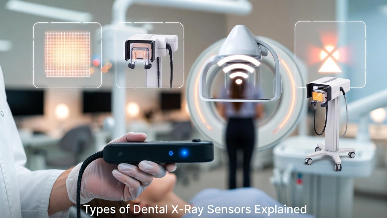
RVG Sensor vs PSP Scanner
An in-depth structural comparison analyzing image latency, spatial resolution, wear-and-tear durability, and long-term ROI parameters for modern practices.
⏱️ 12-14 Min Read
✓ Data-Driven Practice Insights
⚡ The Executive Summary
When evaluating an **RVG Sensor vs PSP Scanner**, the choice boils down to a balance between **speed** and **flexibility**. **RVG (Radiovisiography) sensors** use direct digital chips (CMOS) that deliver crystal-clear images to your monitor instantly (under 2 seconds), making them unbeatable for fast-paced procedures like root canals or implant placements. However, they are rigid and thick. **PSP (Phosphor Storage Plate) scanners** use thin, cordless, flexible plates that handle just like traditional film, offering superior patient comfort—especially for children or patients with strong gag reflexes. They require a manual step where plates are fed into a central laser scanner, but a single scanner can support an entire multi-surgery practice.
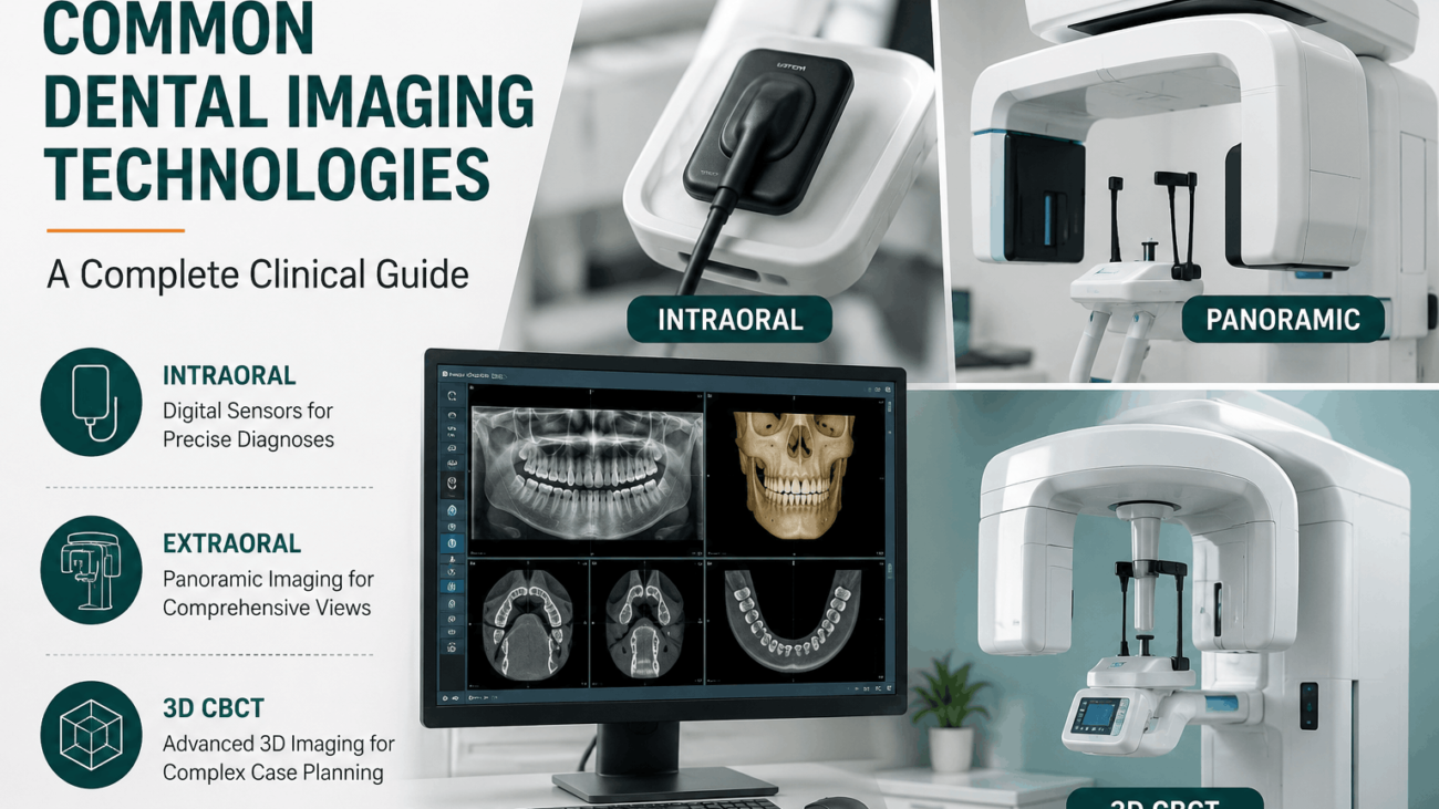
1. Deep Dive: RVG Direct Digital Technology
**RVG (Radiovisiography)** sensors are the standard choice for direct digital intraoral radiography. These devices house a solid-state sensor chip—typically built on **CMOS (Complementary Metal-Oxide-Semiconductor)** architecture—inside a sealed, liquid-proof plastic shell.
The core advantage of an RVG setup is its **real-time image delivery**. Because the sensor remains hardwired via a durable USB cable directly to the computer, captured images display on your chairside monitor in under two seconds. This completely eliminates wait times, allowing dental teams to view sharp structures instantly.
Furthermore, top-tier RVG sensors deliver incredibly high spatial resolution, frequently exceeding **20 to 25 line pairs per millimeter (lp/mm)**. This level of detail makes them essential for high-precision diagnostic work, such as verifying tiny root canal apex lines or monitoring early bone integration around implant threads.
2. Deep Dive: PSP Indirect Imaging Systems
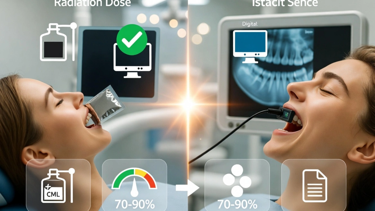
**PSP (Phosphor Storage Plate)** systems offer an indirect path to digital dental imaging. Instead of a thick, wired silicon block, a PSP setup utilizes thin, flexible plates coated with a layer of photostimulable barium fluorohalide phosphors.
When the x-ray hits the plate, the phosphor crystals trap the radiation energy, creating a latent “hidden” image on its surface. The assistant then takes the cordless plate out of its protective hygiene sleeve and places it into a mechanical laser scanner. The laser reads the trapped energy data, converts it into a digital image file for your screen, and automatically erases the plate with white light so it is ready to be sterilized and used again.
While this scanning loop adds a minor delay (typically 10 to 30 seconds depending on the scanner model), the cordless plates look, flex, and handle just like traditional analog dental film. This design makes them highly versatile and remarkably comfortable for patients.
3. Side-by-Side Architectural Evaluation Matrix
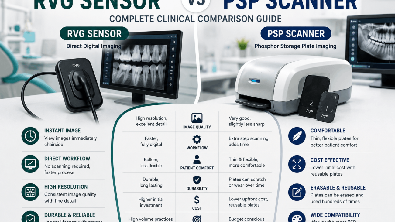
To help you weigh the structural and performance trade-offs of an **RVG Sensor vs PSP Scanner**, this matrix compares their core specifications side by side:
| Performance Metric Focus | Direct RVG Sensor Technology | Indirect PSP Scanner Systems |
|---|---|---|
| Image Processing Speed | **Instantaneous** (< 2 seconds); direct data link. | **Delayed** (10–30 seconds); requires laser scanning. |
| Physical Comfort & Flexibility | Rigid, thick plastic shell; attached to a USB cord. | **Thin, flexible, and completely cordless** plates. |
| Maximum Resolution (lp/mm) | Higher peak resolution (**20 to 25+ lp/mm**). | Excellent diagnostic resolution (**15 to 20 lp/mm**). |
| Sizing Variations Available | Limited (typically Size 0, Size 1, and Size 2). | Comprehensive (**Size 0, 1, 2, 3, and 4 occlusal**). |
| Long-Term Durability Risks | Cable stress breaks or sensor drops can ruin the unit. | Plates scratch over time and need periodic replacement. |
| Multi-Operatory Sharing | Requires moving the sensor or buying units for each room. | **One central scanner** easily processes plates for multiple rooms. |
4. Patient Ergonomics & Clinical Workflow Impact
Choosing between these technologies heavily influences both your daily clinic pacing and your patients’ overall comfort during treatment:
- The Patient Comfort Factor: Because RVG sensors are thick and unyielding, positioning them in patients with small arches, shallow palates, or large bony exostoses (torus mandibularis) can trigger severe gag reflexes or cause mild tissue bruising. On the other hand, cordless PSP plates bend slightly to match the contour of the jaw, ensuring an easy, pain-free experience for pediatric or sensitive patients.
- The Real-Time Workflow Advantage: For procedures like endodontic root treatments, checking an intermediate file instantly with an RVG sensor keeps the workspace efficient. The doctor can confirm instrument depths with the file still in place, without breaking concentration. Using a PSP system here requires taking the plate out, walking it over to a scanner, waiting for processing, and returning to the chair—which adds up over a busy day.
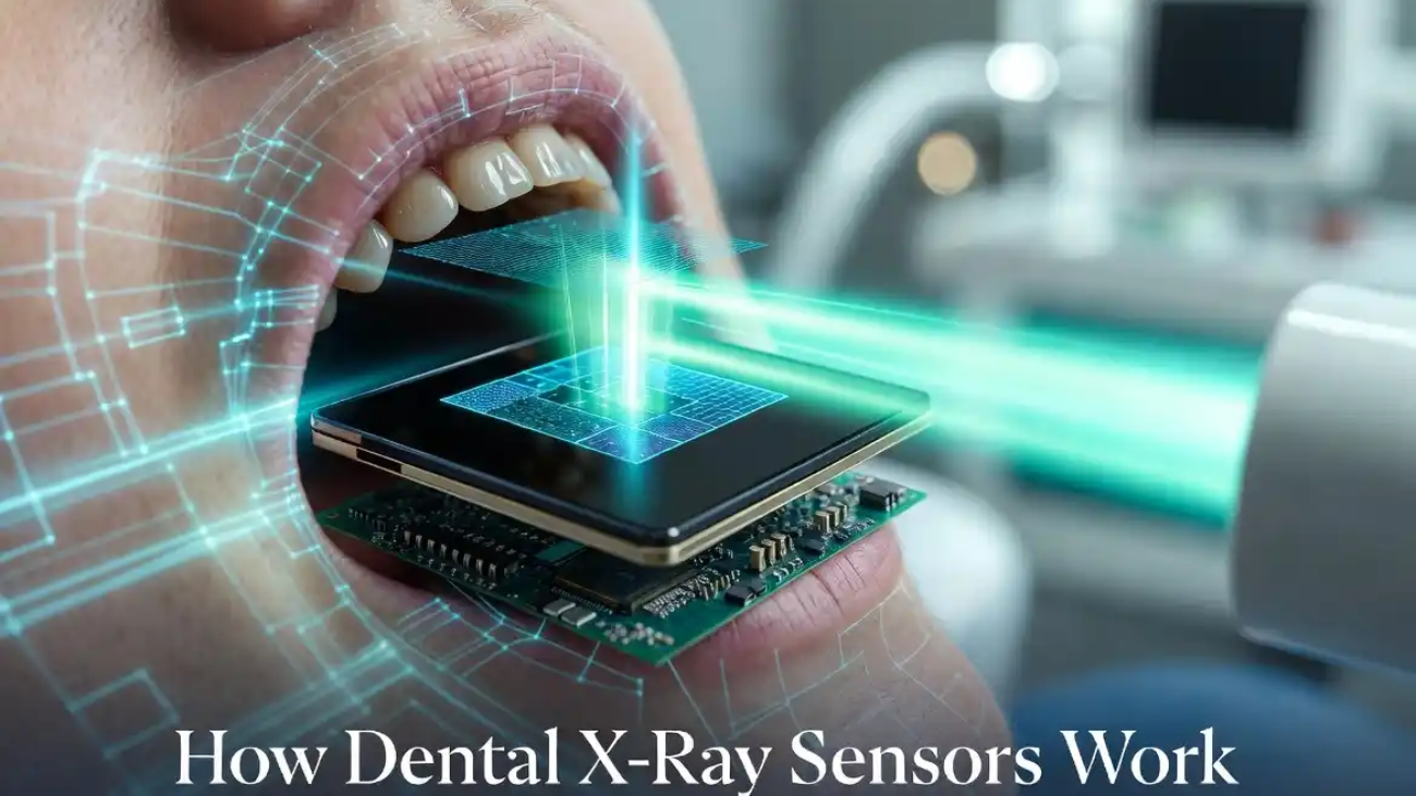
🔬 Go Deeper Into Diagnostic Physics: Want to see exactly how these low-dose systems turn minor photon signals into crisp images? Read our comprehensive technical guide explaining how dental x-ray sensors work to learn about internal scintillator screens and direct conversion engineering.
5. Financial ROI & Buyer’s Decision Framework
To optimize your investment, evaluate the equipment through the lens of your practice’s specific setup and long-term financial budget:
When to Invest in RVG Sensors:
Choose an RVG configuration if you operate a fast-paced single-chair setup, handle complex endodontic treatments daily, or want to eliminate manual scanning steps entirely. It requires a higher upfront cost per room, but saves significant staff time over its lifespan.
When to Invest in a PSP Scanner Unit:
Choose a PSP system if you manage a larger multi-operatory clinic where buying separate sensors for every room is budget-prohibitive. A single PSP scanner can effortlessly support up to 4 or 5 operatories via network sharing. It is also the ideal choice for family practices that require true Size 4 occlusal views or need maximum comfort for young children.
6. Frequently Asked Questions
What happens if a PSP plate gets scratched during handling?
Scratches create small visual lines on future images, which can mimic fractures or decay. Luckily, individual PSP plates are highly affordable and easy to replace. This contrasts with RVG sensors, where a severe cable break or dropped chip can require replacing the entire expensive system.
Can I use a combination of both RVG and PSP technologies in the same clinic?
Yes, many modern clinics utilize a hybrid model. They place fast RVG sensors in dedicated surgical or endodontic rooms for real-time tracking, while utilizing a central PSP scanner to process routine preventive bitewings and pediatric exams comfortably.
Which option exposes patients to less diagnostic radiation?
Both systems are exceptionally safe and offer massive radiation reductions (up to 80-90%) compared to old film methods. RVG sensors are slightly more sensitive to incoming x-ray photons, meaning they can operate with minorly shorter pulse times than phosphor plates.
Upgrade to the Perfect Digital Imaging System
Ready to optimize your practice? Whether you want the blistering fast speed of premium digital RVG sensors or the versatile multi-room sharing of an ultra-high-resolution PSP scanner, SwatDental has you covered.